Autodesk Fusion for Circuit design

Circuit design software

Fusion is an all-in-one circuit design program for schematic capture, simulation, and PCB integration. Powerful, comprehensive, connected, and easy-to-use tools for every circuit board engineer.

circuit-design-manufacturing-treau

What is circuit design?

Circuit design involves the creation of a schematic that acts as a blue print, showing how components connect to form the desired function. This process involves choosing the right parts and planning how everything connects. It also includes testing and making changes so that the design works well and is reliable before building it. Good circuit design is key to making electronics that work smoothly, are efficient, and can be manufactured without problems.

Circuit design software helps create and check electronic circuits by allowing users to draw schematics, run simulations, and design the physical PCB layout all in one place. Unlike basic electronic design programs, circuit design software includes features like design rule checks, signal testing, and automated routing.

Iterate employee using Autodesk Fusion for circuit design

Why choose Autodesk Fusion for circuit design?

Using multiple tools for your electronics circuit design needs is inefficient. Autodesk Fusion is all-in-one circuit design software that combines schematic capture, PCB layout, and 3D mechanical design within a single platform. This integration simplifies the entire circuit design process, so users can easily create, test, and simulate circuits. Fusion is designed to handle everything from simple circuits to complex systems for more streamlined workflows and the elimination of disconnected tools.

Fusion is a complete circuit design program with real-time simulation features such as SPICE analysis, signal integrity, and thermal checks. Cloud collaboration and data management tools allow teams to work together from anywhere, with version control and multi-user design access enhancing coordination.

Fusion can also generate manufacturing outputs like Gerber files, drill files, and BOMs. It's a powerful choice for efficient, modern electronic circuit design programs that meet today’s product development demands.

Autodesk Fusion circuit design software solutions

Cloud-based 3D CAD, CAM, CAE, PCB, and PDM software for product design.


Gain access to advanced design and simulation tools.


Benefits of Autodesk Fusion for circuit design

Streamline the design process

The advanced circuit design tools in Fusion include real-time design validation, 3D visualization, and simulation capabilities, making it easy to go from design to manufacture.

Improve product perfomance

Fusion includes simulation capabilities that allow you to test your design and identify potential issues before building the circuit.

Access comprehensive component libraries

Fusion electronics provides an extensive repository of components. Partners such as Ultra Librarian and SnapEDA have created Fusion add-ins to help you quickly build your components.

Export standardized file formats

Fusion electronics can export designs in various standard formats such as Gerber, ODB++, including Ansys export for simulations and analysis. 

Core features of Fusion circuit design software

Circuit design software, Fusion offers a rich set of features to streamline the entire electronic circuit design process. 

library-package-editor

Schematic capture and library package generator

Easily edit schematics and select components from extensive IPC-compliant libraries. The built-in library package generator automatically creates footprints and 3D models based on component details, saving time and improving accuracy.


Advanced routing in Autodesk Fusion 360 for circuit boards

Advanced routing

For PCB layout, Fusion offers advanced routing tools including live Design Rule Checks (DRC), quick route, group route, and violator modes. These features make it easier to achieve precise and efficient routing, even for the most complex boards.


ecad-mcad-collaboration

ECAD/MCAD collaboration

Fusion supports ECAD/MCAD collaboration, so electronic circuit and mechanical design teams can work together in real time. They can share designs, review updates, and track versions without extra steps. This removes the need for file conversions and makes communication easier for faster and more accurate product development.


Autodesk Fusion, an electronic circuit design program

How to optimize your electronic circuit design workflow with Fusion

Fusion is an electronic circuit design program that integrates design for manufacturing (DFM) checks directly into the workflow, helping reduce costly errors early in the process. These automated checks validate designs against manufacturing constraints, preventing issues that can delay production or increase costs. By catching potential problems before fabrication, Fusion saves time and money while ensuring high-quality, reliable circuit boards.

Cloud-based collaboration allows teams to work together from anywhere in real time. This speeds up decision-making, streamlines feedback, and keeps everyone on the same page with version control and multi-user access. Designers and engineers can share updates seamlessly, reducing bottlenecks and accelerating time-to-market for electronic products.

The unified ECAD + MCAD environment in Fusion eliminates the disconnect often found between electrical and mechanical teams. By combining electronic circuit design with mechanical design tools in one platform, Fusion offers the easy synchronization between PCB layouts and 3D mechanical models. This integration helps prevent costly fit and clearance errors, improves communication, and ensures the final product’s electronic and mechanical parts work perfectly together from the start.

Circuit design for consumer products

Product designers require solutions that help them bring consumer products to market faster and to easily transition from design to production.  Autodesk Fusion enables seamless integration of 3D design and electronics circuit design.

  • Iterate faster with simultaneous collaboration capabilities
  • Minimize delays with ECAD/MCAD integration
  • Simplify project communications with connected teams in one platform
Analog vs. digital circuit design

What are the types of circuit design?

In electronics, circuit design includes two primary types: analog and digital.

Analog circuit design focuses on continuous signals that vary smoothly over time, often involving amplification, filtering, and signal conditioning. These circuits work with components like resistors, capacitors, and operational amplifiers to process real-world signals such as sound and temperature. Designing analog circuits is typically more complex because they require careful management of noise, signal distortion, and power efficiency to achieve precise and stable operation.

Digital circuit design deals with discrete signals represented by binary states—ones and zeros. Digital circuits use logic gates, microcontrollers, and other digital components to perform operations such as arithmetic, control, and data processing. Compared to analog, digital circuit design is often simpler and benefits from numerous automated electronic circuit design programs for rapid prototyping and simulation. Many products use both, requiring careful integration to avoid interference, and ensure reliable performance.

Circuit design software and circuit design programs help engineers navigate these challenges by providing comprehensive tools to create, test, and optimize both analog and digital circuits efficiently.

Mechanical & Electrical design

Workflow for electrical and mechanical design

The ECAD/MCAD workflows in Fusion bring electronics and mechanical design together in one powerful circuit design software solution. Because everything is unified, design changes are adopted instantly—without the need for file conversions or translations.

When you modify a circuit design in the assembly workspace, those updates automatically are reflected in the PCB workspace, making Fusion the only circuit design program that seamlessly connects electronics, mechanics, and manufacturing.

This integration is what sets it apart from other electronic circuit design programs - accuracy, speed, and collaboration across every stage of development.

Try Fusion circuit design software today

Start your free trial of Fusion, the all-in-one circuit design program that goes beyond traditional electronic circuit design programs.

Free circuit design software

This free version for hobbyists and makers includes 2 schematic sheets, 2 signal layers, and 80-cm2 board area.


We offer free circuit design software for students and educators around the world.


Circuits on Tinkercad

Circuits on Tinkercad

Circuits empower you to bring your ideas to life with free, easy-to-use online tools.

  • Simulate and program Arduino and breadboard components
  • Use standard modules to build complex circuits
  • Create and explore circuits then export to PCB design software, like Autodesk Fusion

Circuit design basics for electronics beginners

PCB layout basics

The printed circuit board (PCB) layout brings your circuit design to life in its physical form. Learn more about the PCB layout process and how to design your own.


Circuitry schematic design basics

The schematic design defines connectivity between your electrical component symbols. Learn more about the schematic design process and how to design your own.


SPICE simulation basics

SPICE simulation allows you to analyze voltage and current performance in your circuit design. Learn more about SPICE and how to run your first SPICE simulation.


Circuit design software resources

Electronic circuit design involves ideation, creation, and revision. Learn about PCB design and the circuit design process.


Learn how to make your first high-speed PCB design a success by minimizing crosstalk, EMI, and more.


Learn how Autodesk Fusion provides you with the necessary routing tools and environment settings to make interactive routing easy and efficient.


Use these top 10 PCB routing tips to make your first PCB layout a success.


Learn how to design your printed circuit board (PCB) layout with these tips for routing, component placement, heat dissipation, and more.


By simulating the flow of air, heat transfer, and other factors, identify potential issues and optimize designs for maximum efficiency. 


Circuit design software frequently asked questions (FAQs)

How do I choose the right circuit design software?

Searching for the correct circuit board design software can be daunting. Remembering that circuit board design is one step in developing product solutions. This evolving step must collaborate with many other engineering disciplines, especially mechanical engineers. You need to be able to design and create high-quality designs and streamline your workflow with the right software. A solution that requires no file conversion with seamless electromechanical capabilities, integrated versioning, and collaboration features are crucial. That allows you to work with different team members, access your design from anywhere and track changes easily. In addition, you want software that is easy to use and navigate so that you can focus on the design process. Autodesk Fusion is a great solution!

How much does circuit design software cost?

Autodesk Fusion electronics is circuit design software. Subscribe to affordable monthly or annual options, starting as low as per month. Fusion 360 electronics is also free for personal use and qualifying startups.

Can I perform simulations on my circuit design?

Yes, Fusion includes simulation capabilities that allow you to test your design and identify potential issues before building the circuit board.

What collaboration features are available in Autodesk circuit design software?

Autodesk Fusion includes a modern, collaborative environment to connect teams and stakeholders. You'll gain the ability to:

  • Manage how internal and external stakeholders interact with your data
  • Capture and share feedback from any device using comments and markups
  • Access your data on any device
  • Share public previews 

Is circuit design software easy to learn?

Yes, Autodesk Fusion electronic circuit design software is easy to learn. It includes a user-friendly interface, access to self-paced learning, product documentation, and in-product learning content.

Can I import my existing schematics and designs into a new circuit design software?

If you're currently working with EAGLE design or libraries, importing will not be necessary because Fusion electronics is 100% compatible with fusion.  You can decide to upload them or simply open them in Fusion and continue to work. For further detail consult the Migration guide we have made available.

What is circuit design software?

Circuit design software is a tool that engineers use to design and test electronic and electrical circuits. It allows for the creation of schematic diagrams where the components of a circuit can be represented using symbols, and their connections can be mapped out.

How do you design a circuit?

Designing a circuit involves several steps. Here's a general overview of the process:

1. Define the purpose of the circuit: Understand what the circuit is supposed to do. This includes knowing the inputs and desired outputs. 

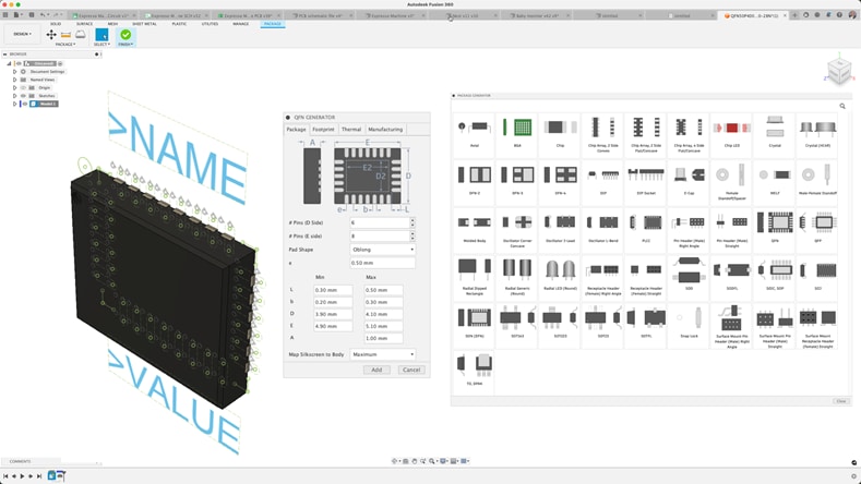
2. Design the circuit schematic: Based on the requirements, start designing the circuit on paper or using a circuit design software. This involves selecting the right components (like resistors, capacitors, transistors, etc.) and connecting them correctly.

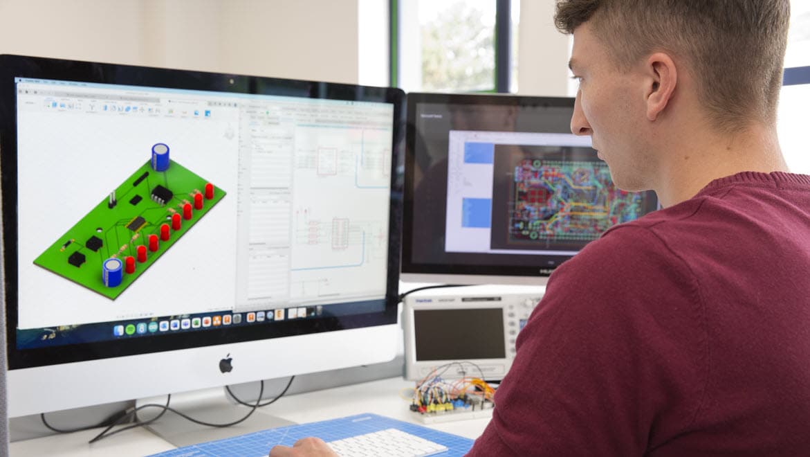
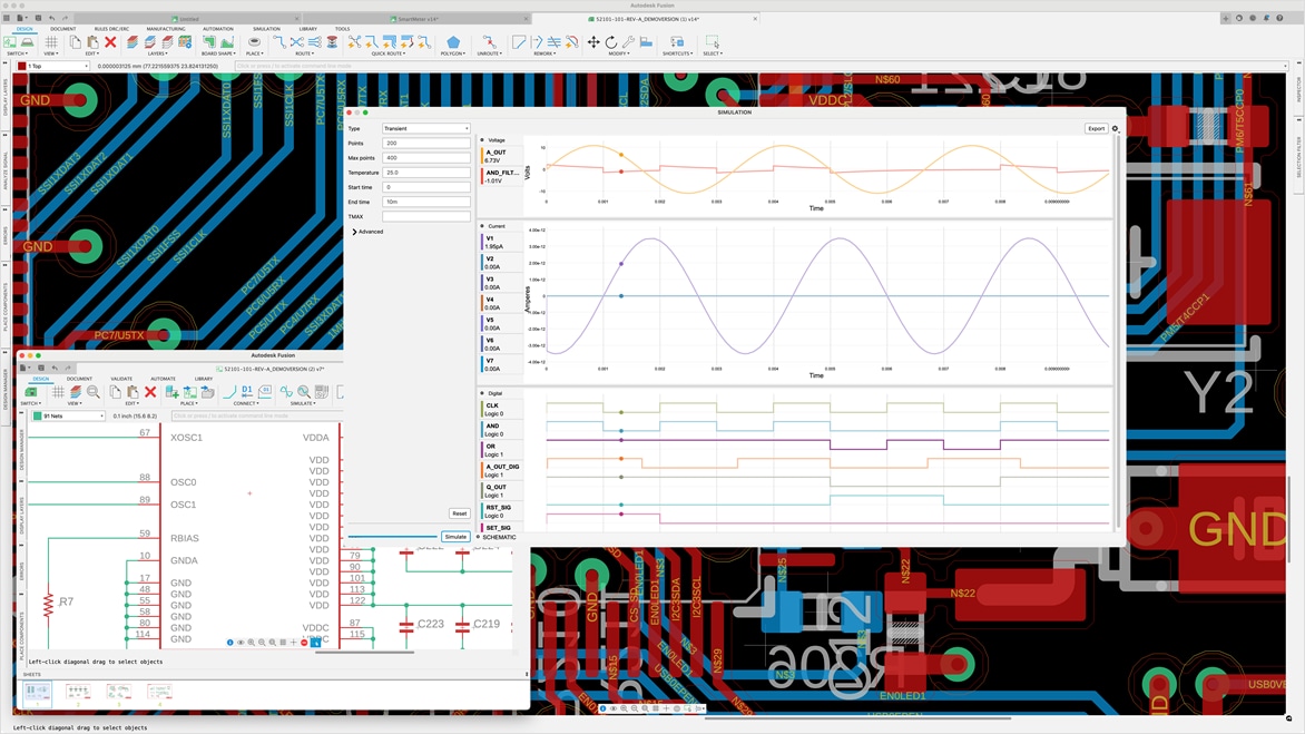
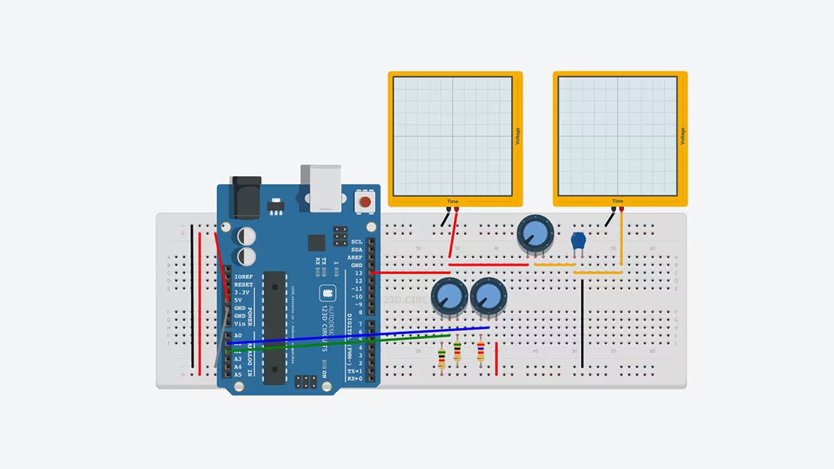
3. Simulate the circuit: Using circuit simulation software like Autodesk Fusion, validate that your circuit works as intended. This step can help you identify and fix potential issues without having to build a physical circuit.

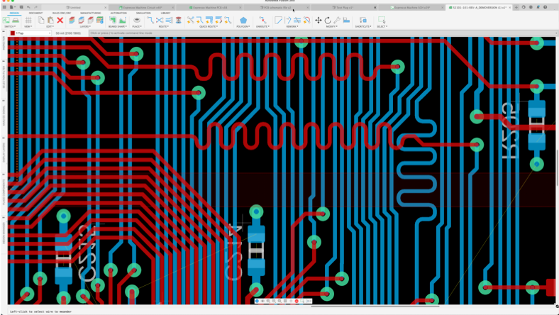
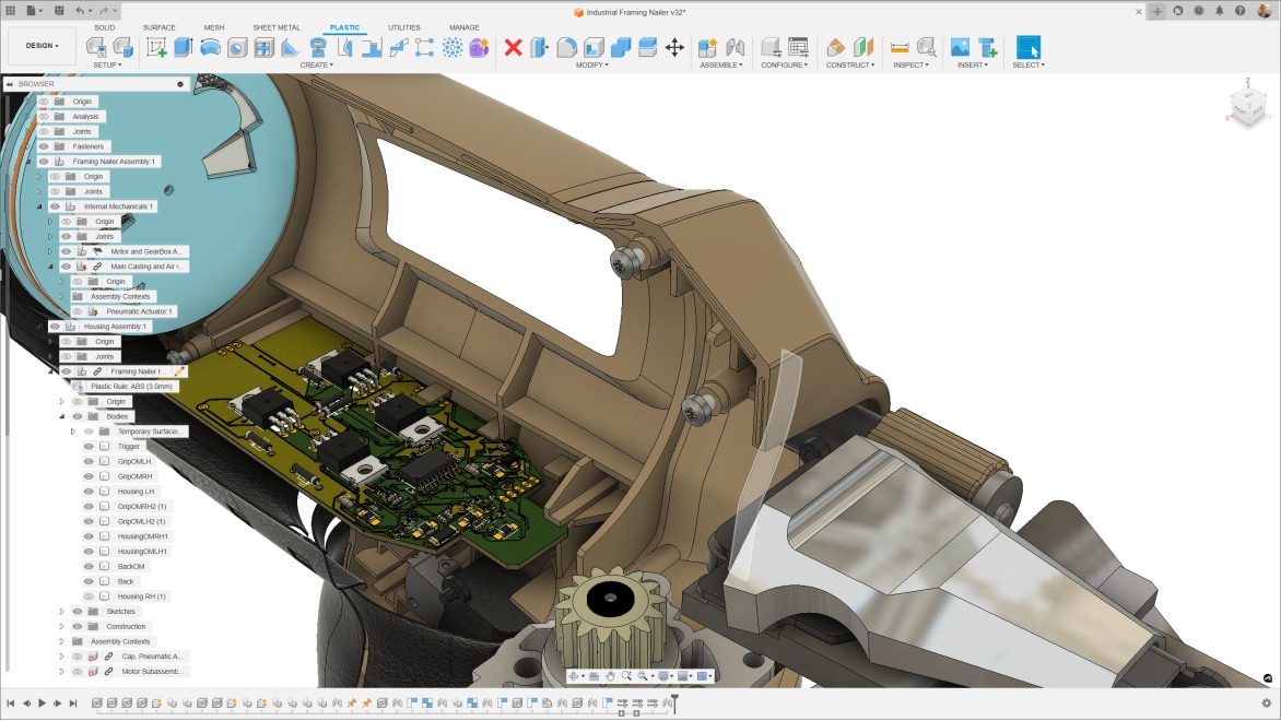
4. Create a PCB layout: Once your schematic design is finalized and simulated, you can proceed to design the Printed Circuit Board (PCB). This involves deciding where each component will go on the board and how they will be connected.

5. Fabricate the PCB: After finalizing the PCB layout, you can have the PCB manufactured. This process involves etching the copper layers to create the necessary pathways for electricity, and drilling holes for component leads.

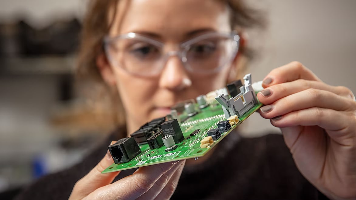
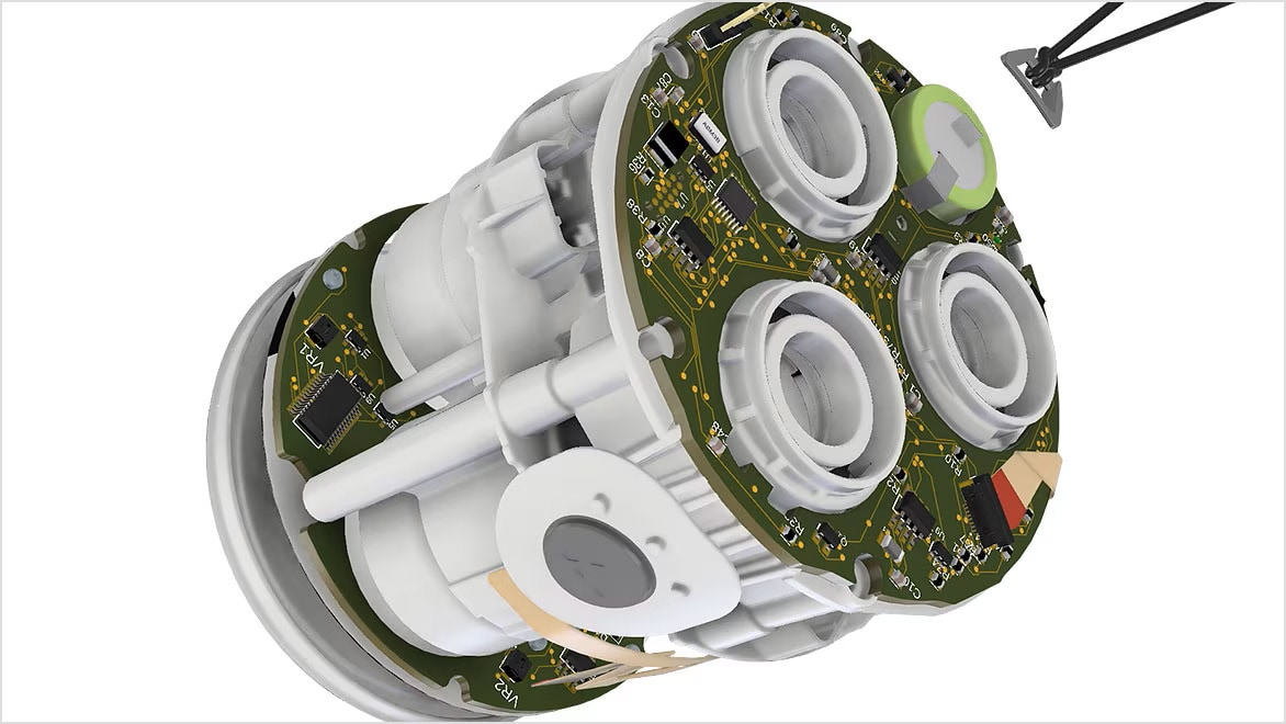
6. Assemble and test the circuit: Once the PCB is ready, solder all the components onto the board following the layout. After assembly, test the circuit to ensure that it functions as expected.

Throughout this process, you may need to iterate on your design several times to get the desired results. Circuit design software like Autodesk Fusion can be very helpful in this process, allowing you to design both the schematic and the PCB layout, and even providing tools for circuit simulation.

See more FAQ